This condition will exist if there is leakage at the flat seat for the amplifier solenoid valve. At idle injector amplifiers are not turned on, thus little to no leakage should be noted out the return line.
Note: When measuring needle/amplifier return flow, both measurements must be completed at the same time, but in separate containers. If these instructions are not followed, incorrect return flow measurements will occur.
Amplifier Measurement Setup
Setup as follows:
- Drain fuel system.
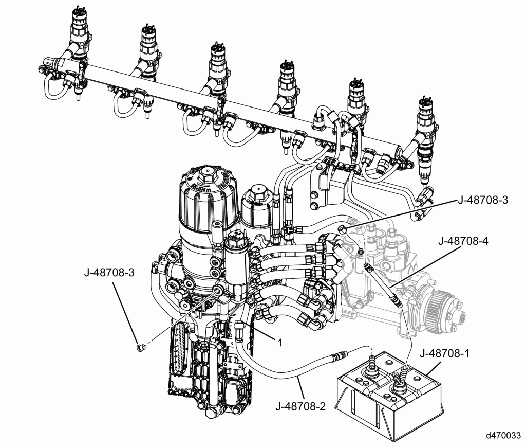
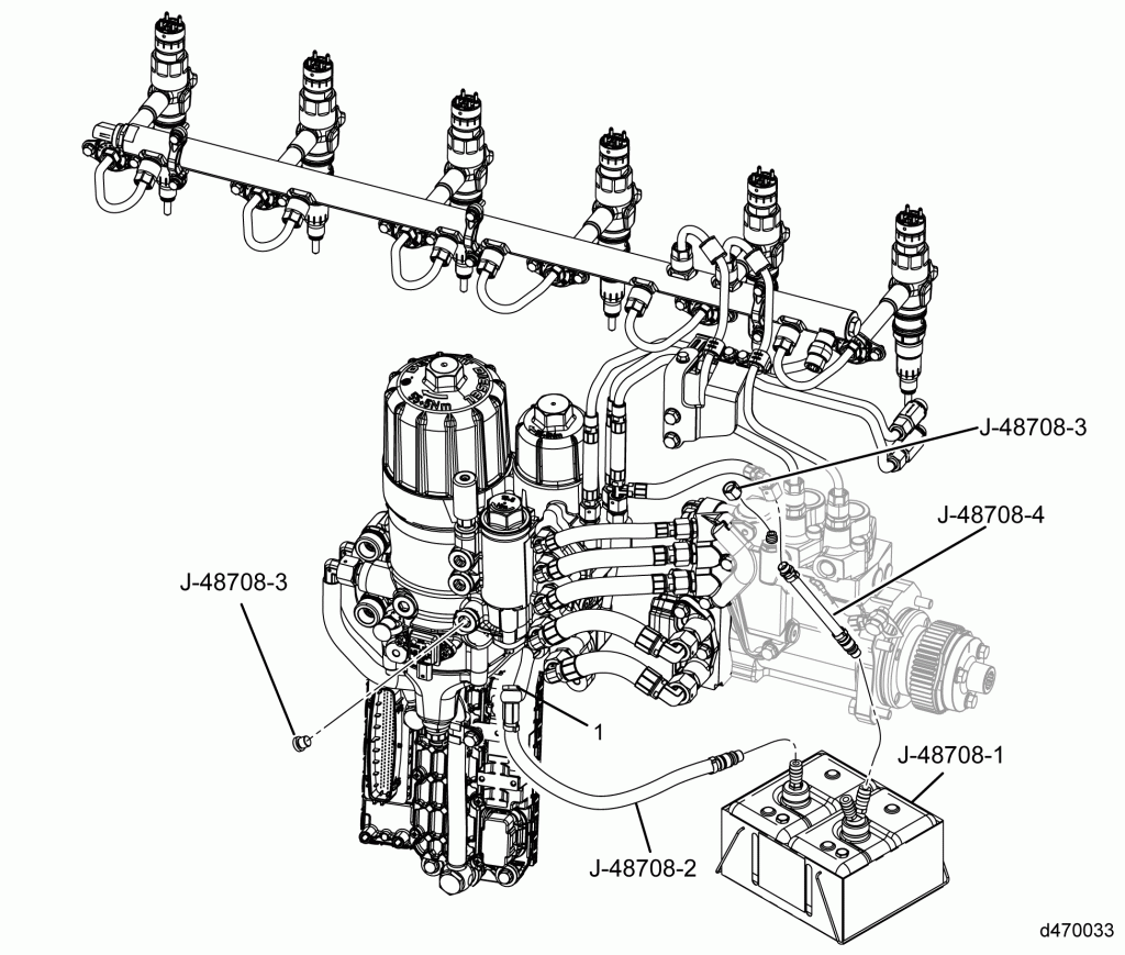
- Remove banjo bolt attaching the amplifier return line (1) to the fuel filter module.
- Using the short banjo bolt supplied in J-48708, plug the opening in the fuel filter module.
- Install the banjo bolt line J-48708-2 to the amplifier return (1) line. The original banjo bolt and new seal rings must be used.
- Attach the opposite end of the clear return line to the J-48708 container.
Needle Measurement Setup
Setup as follows:
- Remove the needle return line from the high pressure manifold located on the high pressure pump.
- Using one cap supplied in the J-48708, cap the fitting at the high pressure manifold.
- Connect needle return line to the clear return line J-48708-4 supplied in kit.
- Attach opposite end of the clear return line J-48708-4 to the opposite J-48708 container.
Return Flow Test
Test as follows:
- Prime fuel system.
- Start engine.
- Measure the amplifier return flow from the clear return line (J-48707) to the container (J-48708).
- The maximum allowable amplifier leakage rate at idle is 15 liters per hour (250 mL per oneminute).
- If the volume is within specifications the system passed, return system to original condition.
- If the volume is out of specification, go to next step.
- Using DDDL 7.0 read parameters “Idle Speed Balance Values” under “Instrumentation” section for all six cylinders. Refer to “16.12.1 Checking ISC Values” “Checking ISC Values.”
- Turn engine OFF and wait five minutes to service any components of the high pressure circuit.Note: System may contain residual high pressure when engine is turned off. Allow the residual pressure to bleed off for five minutes.
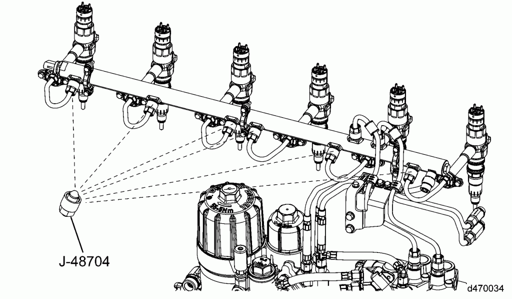
- Disconnect #1 (or next one in sequence) injector high pressure line.
- Install J-48704 rail plug on to the fuel rail and torque to 40 Nm (30 ft/lb).
- Start engine.
- Measure the flow from the clear return line to J-48708 container during a one minute time frame and note the flow rate in the following chart.
Leakage Rate Worksheet Total Leakage Rate (from step 4)
____________ ML per minute ____________ Ounces per minute Capped Cylinder Leakage Rate Was a drop of more than 50ML (1.7 ounces) compared to the Total Leakage Rate noted? Cylinder #1 _____________ ML per minute YES NO _____________ Ounces per minute Cylinder #2 _____________ ML per minute YES NO _____________ Ounces per minute Cylinder #3 _____________ ML per minute YES NO _____________ Ounces per minute Cylinder #4 _____________ ML per minute YES NO _____________ Ounces per minute Cylinder #5 _____________ ML per minute YES NO _____________ Ounces per minute Cylinder #6 _____________ ML per minute YES NO _____________ Ounces per minute - Have all the cylinder flow measurements been recorded?
- If Yes, go to next step.
- If No, go to step 7 .
- Replace suspect injector causing a drop of more than 50 ML (1.7 ounces) compared to the “Total Leakage Rate” value. Once the injector is replaced, go to step 4 to recheck the system and verify repairs.


