Troubleshooting SID 243
The following steps will troubleshoot SID 243.
243 12 – Cruise Control Switch SET and RES Contacts Closed at the Same Time
Perform the following steps to troubleshoot a Cruise Control Switch SET and RES Contacts Closed at the Same Time fault.
- Turn the ignition on and set the cruise control switch to the OFF position. Do not start the engine, since all troubleshooting will be done with the engine off.
- Note the driver display console.
- If the RES status is not displayed, go to step 3 .
- If the RES status is displayed, go to step 5 .
- Check the cruise control switch status.
- If the switch status is not displayed as “SET,” contact Detroit Diesel Technical Service.
- If the switch status is displayed as “SET,” go to step 4 .
- Unplug the cruise control switch.
-
- If the status of the SET switch is displayed as “OFF,” replace the cruise control SET/RES switch. Erase fault code memory.
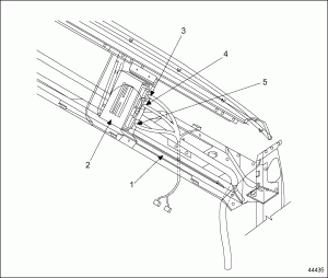
- If the status of the SET switch is displayed as “ON,” repair short to ground in 18-pin connector wire 440E. See Figure “Location of DDEC-VCU and Wiring Harness Connectors” for wiring harness connector locations and see Figure “Connector Positions on DDEC-VCU” for connector positions on DDEC-VCU. Erase fault code memory.
1. Passenger-Side Dash 4. 18-Pin Connector (VC3) 2. DDEC-VCU 5. 21-Pin Connector (VC1) 3. 15-Pin Connector (VC4) Figure 1. Location of DDEC-VCU and Wiring Harness Connectors
1. 21-Pin DDEC-VCU Connector (VC1) 3. 15-Pin DDEC-VCU Connector (VC4) 2. 18-Pin DDEC-VCU Connector (VC3) 4. DDEC-VCU Figure 2. Connector Positions on DDEC-VCU
-
- Unplug the RES switch.
- If the status of the RES switch is not “RES,” replace the cruise control SET and RES switch. Erase fault code memory.
- If the status of the RES switch is “RES,” repair short to ground in 18-pin connector wire 440F. Erase fault code memory. See Figure “Location of DDEC-VCU and Wiring Harness Connectors” for wiring harness connector locations and see Figure “Connector Positions on DDEC-VCU” for connector positions on DDEC-VCU.

