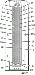
The engine mounted Motor Control Module (MCM) includes control logic to provide overall engine management. See Figure “Motor Control Module” .
| 1. 21–pin Connector (OEM Responsibility) | 2. 120–pin Connector (Detroit Diesel Responsibility) |
Figure 1. Motor Control Module
Note: Do NOT ground the MCM. This can result in false codes being logged.
The Motor Control Module (MCM) incorporates a heat exchanger which uses fuel to cool the MCM. The top plate of the heat exchanger incorporates the inlet and outlet fitting for fuel supply entering and exiting the heat exchanger. The bottom section of the heat exchanger is incorporated into the MCM housing and is serviced with the MCM.
Section 17.2.1
Engine Harness
The MCM has a 120–pin connector Engine Harness which is factory installed. It also has a 21–pin connector which is the responsibility of the OEM. The pinouts for the 120–pin connector are listed in Table “MCM Connector – DD15 Engine (1 of 4)” , Table “MCM Connector – DD15 Engine (2 of 4)” , Table “MCM Connector – DD15 Engine (3 of 4)” , and Table “MCM Connector – DD15 Engine (4 of 4)” .
The pinout for the 21–pin connector is listed in Table “21–Pin Connector to the MCM” .
Section 17.2.1.1
Connector Brackets
The harnesses on MCM must be bracketed and held secure. The bracket design will change for different engines as the routing is different. The 120–pin connector and the 21-pin connector must be tie-wrapped to the brackets.
Section 17.2.1.2
MCM 21–pin and 31–pin Connectors
The wiring for the VIH 21–pin to the MCM is listed in Table “21–Pin Connector to the MCM” . The side of the connector shown is looking into the pins.
| Pin | Signal Type | Function | Connector |
| 21/1 | CAN2L | Not Used |
Front Looking into the Pins on the Harness |
| 21/2 | CAN2GND | Not Used | |
| 21/3 | CAN2H | Not Used | |
| 21/4 | CAN2GND | Not Used | |
| 21/5 | KL31 | Battery (-) | |
| 21/6 | KL31 | Battery (-) | |
| 21/7 | KL15 | IGN | |
| 21/8 | KL31 | Battery (-) | |
| 21/9 | KL31 | Battery (-) | |
| 21/10 | CAN1GND | Engine CAN Shield | |
| 21/11 | KL30 | Battery (+) | |
| 21/12 | KL30 | Battery (+) | |
| 21/13 | CAN1H | Engine CAN + | |
| 21/14 | KL30 | Battery (+) | |
| 21/15 | KL30 | Battery (+) | |
| 21/16 | CAN1GND | Not Used | |
| 21/17 | BOOT | Not Used | |
| 21/18 | KDiag_S | Not Used | |
| 21/19 | CAN1L | Engine CAN – | |
| 21/20 | KL50 | Crank Start Input | |
| 21/21 | START_B | Crank Activation Output |
The pinout for the 31–pin pigtail on the Engine Harness is listed in Table “31–pin MCM Pigtail Connector” . The OEM is responsible for wiring to this connector.
| 31–pin | 120–pin | Function | DD15 Engine |
| 31/1 | — | Spare | — |
| 31/2 | — | Power Supply (IGN)* | X |
| 31/3 | — | Fuel Heater Supply #1† | X |
| 31/4 | — | Spare | — |
| 31/5 | — | Full Heater Supply #2† | X |
| 31/6 | — | Spare | — |
| 31/7 | — | Power Supply Ground* | X |
| 31/8 | 120/70 | Ether Start | — |
| 31/9 | 120/33 | Fan Control #2 – High of Two-speed Fan or Variable Speed Fan | X |
| 31/10 | 120/98 | Single Speed Fan or Low for Two-speed Fan | X |
| 31/11 | — | Fuel Heater Ground #1† | X |
| 31/12 | — | Spare | — |
| 31/13 | — | Spare | — |
| 31/14 | 120/71 | Water-in-Fuel Sensor Supply | X |
| 31/15 | 120/67 | Water-in-Fuel Sensor Ground | X |
| 31/16 | 120/96 | Engine Brake Solenoid Control | — |
| 31/17 | 120/29 | DOC Outlet Temp Sensor (Exhaust Gas Temperature in Front of Particulate Trap) | X |
| 31/18 | 120/89 | DOC Inlet Temp Sensor | X |
| 31/19 | 120/115 | DPF Outlet Temp Sensor( Exhaust Gas Temperature After Particulate Trap) | X |
| 31/20 | — | Full Heater Ground #2† | X |
| 31/21 | — | Spare | — |
| 31/22 | 120/91 | Power Supply (Eng Brk, Fan, Ether) | X |
| 31/23 | 120/47 | Fan Speed | X |
| 31/24 | 120/88 | Sensor Ground | X |
| 31/25 | — | HDMS Fan Thermal Switch | X |
| 31/26 | 120/57 | Water-in-Fuel Sensor | X |
| 31/27 | 120/86 | TCI Temp | X |
| 31/28 | 120/114 | Sensor Ground | X |
| 31/29 | 120/85 | Sensor Supply | X |
| 31/30 | 120/30 | DPF Outlet Pressure Sensor (Exhaust Gas Pressure After Particulate Filter) | X |
| 31/31 | 120/118 | DPF Inlet Pressure Sensor (Exhaust Gas Pressure Before Particulate Filter) | X |
*Fused at 15 amps
† Optional for MBE 900 and DD15 Engine. Must use 14 AWG wire and fuse at 20A.


